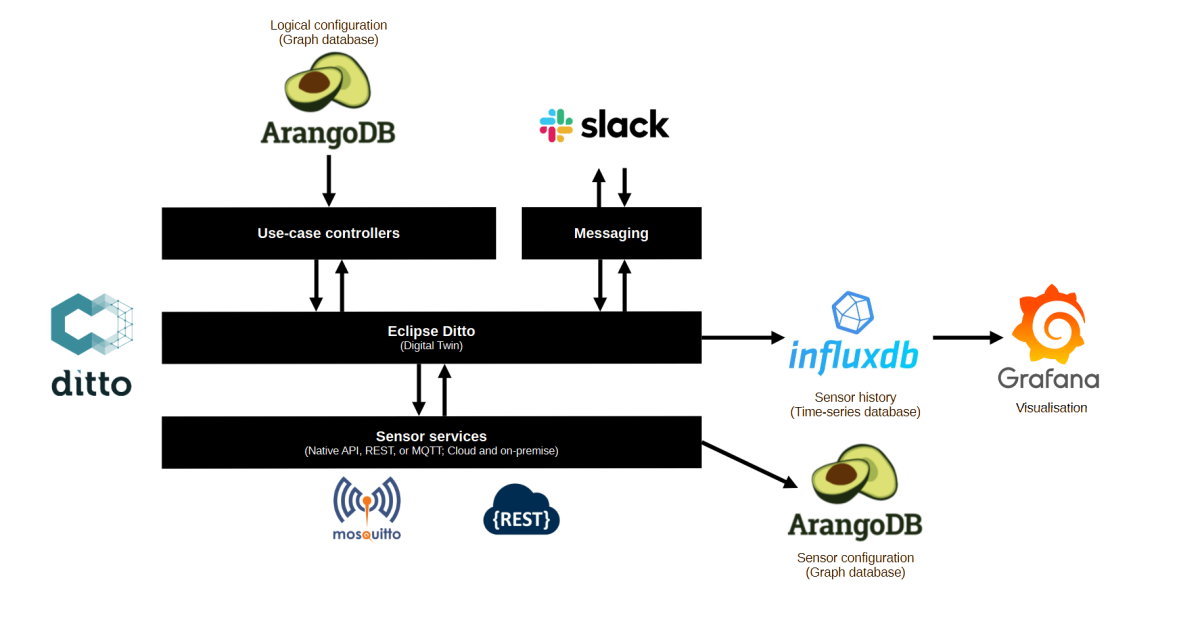
This article describes the components that build up the architecture of my (digital) home.
Logical configuration (ArangoDB): the logical configuration includes the areas (rooms) in the house, the sensors and actors located in those areas, and the “scenes” that can be applied to actors and areas.
Use-case controllers (custom .NET Core worker services): I’ve build a separate micro service for each use-case, for example, controlling lights, planning washer, dishwasher, and dryer, and planning the generation of domestic hot water.
Digital Twin (Eclipse Ditto): the Digital Twin stores the state of all connected sensors and is used by the use-case controllers to consume sensor states or push commands back down to the sensors.
Messaging (Slack): I’m using Slack as a messaging service to interact with my home. Slack informs me on specific state changes in the Digital Twin and I can feed commands in Slack to influence the behavior of my home. I try to minimize this as most decisions should be fully automated.
Sensor services (custom .NET Core worker services): the sensor services read sensor states via open or proprietary protocols. They are also responsible for pushing commands down to actors.
Sensor history (InfuxDB): InfluxDB stores the (relevant) history of the Digital Twin as well as the history from the different energy services that feed directly into InfluxDB.
Sensor configuration (ArangoDB): ArangoDB stores the information needed to communicate with local and cloud-based sensors.
Visualisation (Grafana): I’m using Grafana as a visualisation front-end.
Visualization of the architecture of my digital home.
Are we all in the same place? Do we have the same understanding?
What makes this moment complicated?
What is the uncomfortable truth that I’m not allowing myself to see or accept?
2. Value outcomes
When you value plans more than outcomes it’s easy to mistake effort for achievement.
3. Leverage the brains
You only need three kinds of people in any decision meeting: the people with the authority to say yes, the people with the information or expertise, and the people who have to live with the outcome. If this means leaving out lots of people from a decision team, then think of it as representative rather than direct democracy, says Janice.
4. Make durable decisions
Eliminate waste by changing your standards. Two kinds of waste come into decision making, says Janice – decisions can either be very slow or made quickly but chaotically. In the latter case this is because they may be made unilaterally, made by the wrong people, or with no commitment from others. While such decisions may be fast, productivity will be slow, Janice says.
Durable decisions should balance speed and strength. Two sentences to look out for here are “Can you live with it?” and “Does it move us forward?”, says Janice, these are different from “Do we all agree?” and “Is it the best?”.
“I think most drama comes from difficulties in decision-making,” Janice concludes. “I think decision making is a leadership skill. If you can facilitate great decision-making in a great decision-making process by bringing this more realistic framing to it, then you’re going to improve the culture of your organisations tremendously.”
Summary
Orient honestly
Vision
Point A and point B. Where are we now? Where do we want to be? Relates to Vision.
What makes a good point A? You need to be brutally honest about your status quo. Include any disorder or messiness. Be sure to capture your hardest win, most durable markers of progress, points of tension, messiness, and uncertainty.
What makes a good point B? Point B should be specific enough to guide your actions, but not so specific that it points you towards a single possible outcome.
Outcomes
Concrete and measurable goals are mostly framed as outputs: writing a book, hitting a sales goal, losing weight. When we orient around outcomes we define what we want to have, change, or be, and put loose parameters around that. We decide on an ideal end-state that could come to pass in a variety of ways.
Be happy going to work in the morning.
Quit job/company.
New job & company.
Have less stress, drama, conflict.
Find a new situation; talk with supervisors.
New role at same company; new project with different team.
Manage or mitigate the dysfunctional situation.
Build relationship with coworkers.
Support within current role.
A tool for finding the truth: Five times why
Self deception: we don’t know everything. What do I know? How do I know it?
How do we know we’re not honest to ourselves?
1
WHY is there no coffee in the coffeepot?
Because we’re out of coffee filters.
2
WHY are there no coffee filters?
Because nobody bought them at the store.
3
WHY didn’t someone buy them on the last shipping trip?
Because they weren’t on the shopping list.
4
WHY weren’t they on the shopping list?
Because there were still some left when we wrote the list.
5
WHY were there still a few left when we wrote the list?
uhhhh?
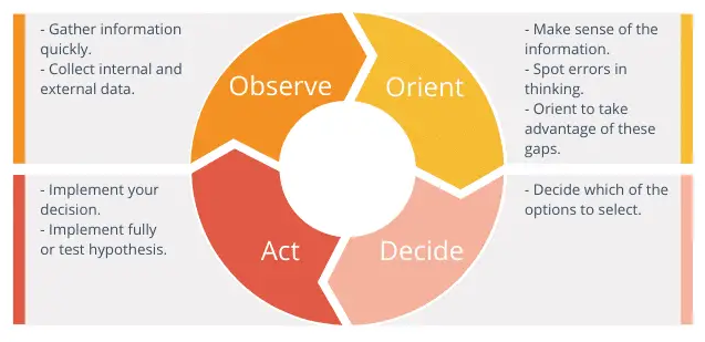
A hyper dynamic world
The OODA loop makes it easier for individuals to decide which actions to take in dynamic situations.
OODA loop example:
Observe: based on many inputs, each day an air mission plan is released that describes what each combat plane will be doing the next day.
Orient: Once the plan is released, a tanker planner team evaluates the needs, assesses where tankers will be needed, and at what exact times in order to keep the combat planes on-mission.
Decide: tankers and personnel are allocated to each of the specified coordinates.
Act: each morning, a tanker plan is submitted for the day’s sorties.
Value outcomes
Everyone takes it on faith that if we execute our little portion of the plan according to the items that were specified up front, then we will necessarily have done the right thing and have delivered the value. When you value planning above outcomes, it’s easy to conflate effort with achievement.
Outcome oriented roadmap
It you spend time doing it, it’s an activity.
The tangible result of that time spend is an output.
The reason for doing those two things is the outcome.
People involved in creating an OORM:
People with the authority to say yes;
People who have relevant knowledge;
People who have to live with the outcome.
Tests to bulltproof the OORM:
Are the outcomes clearly articulated?
How good are your metrics?
Have you articulated risks and mitigations?
Does your roadmap represent an aligned viewpoint?
Is your roadmap easy to discover and consume?
Making outcomes actionable
Provide just enough direction.
OGSM: Objective, Goals, Strategies, Measures.
OKRs: Objects, Key Results
V2MOM: Vision, Values, Methods, Obstacles, and Measures.
Leverage the brains
Leverage the brain in three steps:
Frame the problem
Get the right people in the room
Respect your collaborators
Externalize, Organize, Focus
Externalize (go-wide): the first step is putting as much of the situation as possible into physical space, so that people can literally see what’s going on in each other’s heads. In most cases, externalizing means writing down our thoughts our ideas where others can see and understand them. This can be, for example, in a narrative (Narratives).
Organize (now, decide): next, we make sense of the undifferentiated mess of items we’ve just externalized. The most common approach to organizing is to group items, ideas or subjects into logical sets, for example, by type, urgency, cost, or any other criterion.
Focus (prepare for action): we need to decide what matters based on the organizing. We need to interpret the significance of each group and let that guide us in a decision.
Reinventing “the meeting”
Definition in 1976: A meeting is a place where the group revises, updates, and adds to what it knows as a group. We didn’t have computers, email, text, or video in 1976, so this made sense. Our options for communications and collaboration where very limited, so this was the only efficient format.
Tips on how to run a modern meeting:
Switch up language: let’s move from “agenda” or “topics to discuss” to “work plan”. Let’s stop using “meeting” but use “decision session” or “work session” instead. These small language tweaks set different expectations for how the time will be spend.
Frame the meeting with an AB3: explain point A (start of the meeting) and point B (end of the meeting), and three agreements / methods that you will use to move from A to B.
Make durable decisions
Questions:
It this a decision we can all live with?
If we went in this direction, is that something we could all live with?
These questions widens the aperture of possibility, while reducing the chances that someone will back out later.
Decision-making process
Steps in the decision-making process:
Notice there is a decision to make;
Gather inputs (costs, potential solutions, time frame);
Weighing options (pros and cons);
The moment of choice;
Resourcing (who is going to execute?)
Execution.
It’s fine to move back into a previous step if this feels right.
Durable decisions
Avoid absolutes (find a good enough decision instead of the “right” decision);
Get the facts right (to move quickly, first gather facts and inputs);
Consent, not consensus (agree to disagree);
The right people, but not too many (people with the authority to say yes, people who have subject-matter knowledge, people who have to live with the outcome);
Reduce the scope (break down large decisions into incremental moves);
Mental agility and growth mindset required (if stakeholders come with their mind made up, it will be a difficult discussion).
UBAD
Understanding: stakeholders need to understand what it is you’re proposing. Any decision that is made without understanding is highly vulnerable;
Belief: once a stakeholder understands your thinking, you need to help them believe in it. That means hearing objections, exploring concerns, and satisfying curiosity;
Advocacy: when someone is putting their social capital on the line to spread the idea, you know that they must truly support it;
Decision-making: are stakeholders making decisions in support of the idea? This represents the most enduring form of support.
Writing narratives forces me to focus on the content and the story. The writing process itself triggers a deep thought process and helps me to iteratively improve the story.
A narrative can have different structures. One example is:
In the past it was like this …
Then something happened …
So now we should do this …
So the future might be like this …
Another example of the structure of a narrative:
Context (or question)
Approach (Approaches to answer the question – by whom, by which method, and their conclusions)
Differentiation (How is your attempt at answering the question different or same from previous approaches? Also compared to competitors)
Now what? (that is, what’s in it for the customer, the company, and how does the answer to the question enable innovation on behalf of the customer?)
Appendix
So, why is this 4-6 page memo concept effective in improving meeting outputs?
It forces deep thinking. The 6-page data-rich narratives that are handed out are not easy to write. Most people spend weeks preparing them in order to be clear. Needless to say, this forces incredible, deep thinking. The document is intended to stand on its own. Amazon’s leaders believe the quality of a leader’s writing is synonymous with the quality of their thinking.
It respects time. Each meeting starts with silent reading time. When I asked why they don’t send out the narratives in advance, the response was, “we know people don’t have the time to read the document in advance.”
It levels the playing field. Think of the introverts on your team who rarely speak during a meeting. Introverted leaders at Amazon “speak” through these well-prepared memos. They get a chance to be heard, even though they may not be the best presenter in the organization.
It leads to good decisions. Because rigorous thinking and writing is required – all Amazon job candidates at a certain level are required to submit writing samples, and junior managers are offered writing style classes – team members are forced to take an idea and think about it completely.
It prevents the popularity bias. The logic of a well thought out plan speaks louder than the executive who knows how to “work the halls” and get an idea sold through influence rather than solid, rigorous thinking and clear decision making.
“I didn’t realize how deeply the document culture runs at Amazon. Most meetings have a document attached to them, from hiring meetings to weekly business reviews. These documents force us to think more clearly about issues because we have to get to a clear statement of the customer problem. They also enable us to tackle potentially controversial topics. As the group sits and reads, each individual gets time to process their feelings and come to a more objective point of view before the discussion starts. Documents can be very powerful.”
Roughly 20% of Dutch homes is equipped with solar panels. In Germany the adoption rate of solar panels is roughly 11%. This means that these homes produce power locally, but they hardly use it at the same time when it’s being produced. Only 30% of the produced energy is consumed directly. That means that 70% of the energy consumption is still consumed from the grid.
Metrics
Considering my own installation the numbers are even worse. Only ~20% of the locally produced (10mWh) energy is directly consumed (2Mwh). The real problem is that almost 80% of the consumed energy is consumed from the grid.
Vision
In 2026, three years from now, I want to reduce my grid consumption to 50% (on average, per year).
I have no idea if this is achievable, but it’s good to have a concrete goal. If I figure out I can achieve this in one year, I will increase my ambition.
In order to achieve this vision, I need to increase the direct consumption which will result in a decrease of overall grid consumption.
Steps along the way
To reach this vision, I need to understand at which times energy is already directly consumed and which consumers are causing this consumption. Additionally, I need to understand when energy is consumed from the grid and which consumers are causing this consumption. I’m hoping that, by influencing the consumption patterns of the largest consumers, I can make the first large step.
Year
Grid consumption
Direct consumption
2023 (today)
80%
20%
2024
60%
40%
2025
53%
47%
2026
50%
50%
Overview of yearly goals to reach my vision in 2027.
I expect that the first major improvements will already start paying off in 2024. I’m aiming for a 20% increase in 2024 over 2023. Then the real challenge will probably start.
First analysis of available data
In the first half of the year my system was still in development. After that is has become more stable, which resulted in a stable data collection since June.
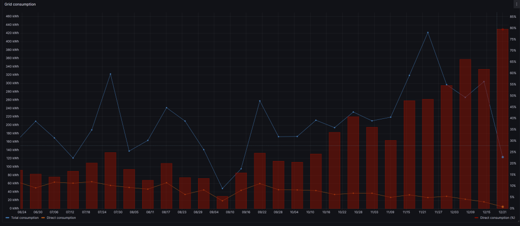
When is direct consumption low?
At this moment I considered one interesting data points per week:
Direct consumption (%) = direct consumption / total production (solar);
The direct consumption (%) in red per week. It’s clearly visible that when the solar production goes down in the winter months, the direct consumption goes up.
Considering the available data I should start trying to focus on the summer months when solar production is high.
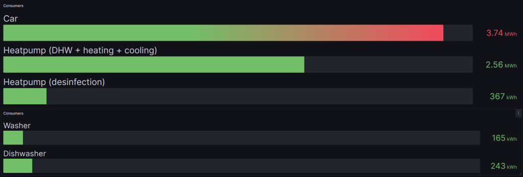
Which are the largest consumers?
Let’s have a look at the usual suspects fist: the car, heatpump, washer, and dishwasher.
The car takes roughly 35% of the yearly consumption. The (combined) heatpump follows with 28%.
Next steps
Considering my vision and the available data I should focus on moving grid consumption for the car and heatpump to direct consumption, especially in the summer months. I will share concrete objectives and key-results for this in a next post.
The InfluxDB start-up script checks if the HTTP service is running by trying to connect to it. However, I have disabled HTTP in my configuration and use HTTPS. This behavior is also described on Github.
You can workaround this issue by adjusting the InfluxDB service configuration file (/etc/systemd/system/influxd.service). The commented out lines are old configuration and replaced by the used lines.
[Unit]
Description=InfluxDB is an open-source, distributed, time series database
Documentation=https://docs.influxdata.com/influxdb/
After=network-online.target

[Service]
User=influxdb
Group=influxdb
LimitNOFILE=65536
EnvironmentFile=-/etc/default/influxdb
ExecStart=/usr/bin/influxd -config /etc/influxdb/influxdb.conf $INFLUXD_OPTS
#ExecStart=/usr/lib/influxdb/scripts/influxd-systemd-start.sh
KillMode=control-group
Restart=on-failure
Type=simple
#Type=forking
PIDFile=
#PIDFile=/var/lib/influxdb/influxd.pid

[Install]
WantedBy=multi-user.target
Alias=influxd.service
Create a test query that summarizes the data that needs to be stored in the downsampled data:
SELECT mean("current_delivery") as "current_delivery", mean("current_usage") as "current_usage", last("total_usage_gas") as "total_usage_gas", last("total_usage_t1") as "total_usage_t1", last("total_usage_t2") as "total_usage_t2", last("total_delivery_t1") as "total_delivery_t1", last("total_delivery_t2") as "total_delivery_t2" FROM energy_p1_actual GROUP BY "name", time(1h) ORDER BY time DESC LIMIT 10
Then, define a continuous query from this:
CREATE CONTINUOUS QUERY "cq_60m" on "P1_External" BEGIN SELECT mean("current_delivery") as "current_delivery", mean("current_usage") as "current_usage", last("total_usage_gas") as "total_usage_gas", last("total_usage_t1") as "total_usage_t1", last("total_usage_t2") as "total_usage_t2", last("total_delivery_t1") as "total_delivery_t1", last("total_delivery_t2") as "total_delivery_t2" INTO "2yr"."energy_p1_history" FROM energy_p1_actual GROUP BY "name", time(1h) END
As our retention policy is set to 2 hours the continuous query will run every two hours to summarize the data.
This is working for me now. However, while I was documenting this process I figured out I might have mixed up the 3DES and RSA certificates in the Mosquitto configuration. Something to look into at a later moment in time.
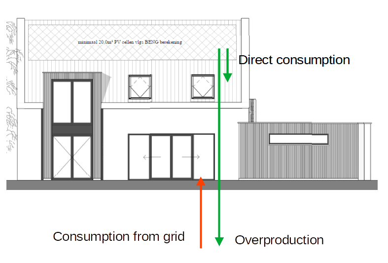
One of the goals of building a digital twin of our house is to reduce our dependence on external energy sources. To achieve this goal, and to validate if my measures are having a positive effect, I need to compute our dependence on external energy sources. Our house will be fully electric, so that makes things a bit easier as I don’t have to take gas into account.
Basically, we will have two sources of energy (the grid and the PV (solar) panels) and one consumer: the house itself, including all the appliances consuming energy.
Energy situation of our future house.
External energy, in this context, is energy consumed from the grid. I calculate the total amount of energy we consume using:
When the PV panels are not producing energy, there will not be any overproduction, and the total_consumption will be equal to the grid_consumption. When there is no grid_consumption and the PV panels are producing sufficient energy to meet the demand, the total_consumption is equal to the pv_production minus the pv_overproduction.
I’m interested in our dependence from the grid. This is then an easy next step:
dependence = grid_consumption / total_consumption
This gives me a number that gives me the amount of energy consumed from the grid related to the total consumption. Initially, I will calculate our dependence based on 30 minute intervals.
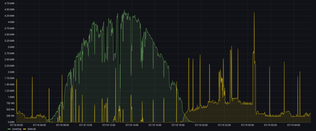
The good news is that I already have the data, but it’s spread over multiple time-series. I’m building a small service that consumes the required data from the time-series, computes the dependence, and writes it back into a new time-series for historic analysis.
Grafana showing pv_overproduction (green) and grid_consumption(yellow).
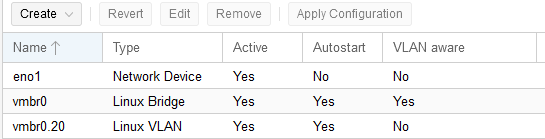
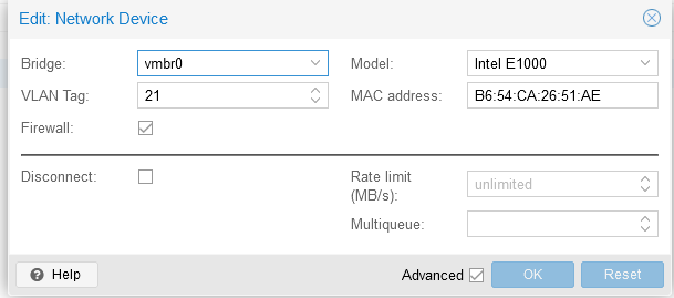
I’m using Proxmox as a hypervisor to run my virtual machines and use two VLANs in my home network: one for normal traffic and one separate VLAN for IoT traffic. Virtual machines should be connected to one of those networks. The normal network is typically untagged (vlan ID 20) while the IoT traffic is tagged with VLAN 21.
Configuration file: /etc/network/interfaces
auto lo
iface lo inet loopback

iface eno1 inet manual

auto vmbr0
iface vmbr0 inet manual
        bridge-ports eno1
        bridge-stp off
        bridge-fd 0
        bridge-vlan-aware yes
        bridge-vids 2-4094

auto vmbr0.20
iface vmbr0.20 inet static
        address 192.168.20.x/24
        gateway 192.168.20.1
This should result in the following Proxmox network configuration:
Proxmox host system network configuration
Now you can easily add a network adapter to a virtual machine and tag it with the correct VLAN.
Virtual machine network adapter configuration, including tagged VLAN.
Manage Cookie Consent
I use cookies to optimise my website and service.
Functional Always active
The technical storage or access is strictly necessary for the legitimate purpose of enabling the use of a specific service explicitly requested by the subscriber or user, or for the sole purpose of carrying out the transmission of a communication over an electronic communications network.
Preferences
The technical storage or access is necessary for the legitimate purpose of storing preferences that are not requested by the subscriber or user.
Statistics
The technical storage or access that is used exclusively for statistical purposes.The technical storage or access that is used exclusively for anonymous statistical purposes. Without a subpoena, voluntary compliance on the part of your Internet Service Provider, or additional records from a third party, information stored or retrieved for this purpose alone cannot usually be used to identify you.
Marketing
The technical storage or access is required to create user profiles to send advertising, or to track the user on a website or across several websites for similar marketing purposes.